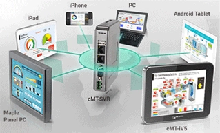
The HMI view of an operator interface terminal, whether on a local
display, mobile tablet, supervisory panel PC, or remote workstation, is
only one view of the important data in an automation system. There are
also; alarm and data logging, database integration, recipe management,
protocol translation and more. cMT Series Products prove to be a
flexible tool in these areas as well. Let's tour a few features
available to manage your data on the cMT products:
Modbus
Gateway
In an ideal world, every machine vendor and systems integrator would use
the same protocol and all equipment would seamlessly communicate with
everything else on a plant floor. More often than not, this is far from
the case. As a plant grows over time and different systems are added,
little thought is given to the process as a whole. You'll often find
different systems, from different manufacturers, speaking different
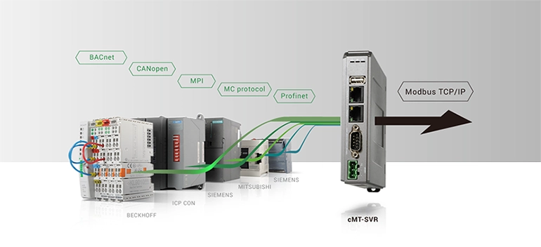
protocols, on different serial busses. Fortunately, cMT products speak
many languages. cMT Series Products can use over 300 protocols on any of
the available com ports, and translate them to the default industrial
standard protocol: Modbus TCP/IP. The cMT device becomes a transparent
protocol translator, allowing upstream SCADA systems to connect to PLCs
as if they were all using the same protocol on the same
bus.
Modbus Communication
Gateway
 Database
Object
Database
Object
Increasingly, data that machines produce needs to be recorded and
preserved. The data may be useful in process improvement or may be
required by regulatory agencies. The cMT products have an object which
allows them to log a data sampling object or an alarm log directly to an
SQL database server over an Ethernet LAN.
This eliminates the need for manually retrieving and entering log files
from each machine independently. Data from many different sources can be
aggregated and stored in one central safe and secure location,
automatically.
Databases and
Recipes
Recipes are a collection of parameters stored in the HMI that can be
transferred to a machine with one press of a button. Different parts may
require different amounts of material, different cook times and
temperatures, or different processing steps. This data often needs to be
shared across multiple machines that may be at different steps in the
process, or may be redundant production lines working on producing the
same or similar products.
SQL databases can act as a storage tank for all machines sharing a
particular recipe database. cMT HMIs can query the database for current
recipe data before sending those parameters to the PLC. This way,
changes only need to be made to this central database, instead of
manually changed in each HMI.
This feature saves time in systems that have many machines sharing many
recipes. The changes, additions, and deletions to the database only need
to be made in one place and are then automatically updated throughout
the system. This ensures production uniformity throughout the system. A
single machine will not get stuck using an outdated recipe simply
because someone forgot to update it.
 Editor")
 Editor")
 Editor")
 Editor")


 New technologies bring new ways of interacting and controlling systems,
but the need for a static HMI that is always ready and available will
not go away. While cMT Series HMIs enable new and exciting features, the
cMT Series also does not compromise on fulfilling this vital role.
New technologies bring new ways of interacting and controlling systems,
but the need for a static HMI that is always ready and available will
not go away. While cMT Series HMIs enable new and exciting features, the
cMT Series also does not compromise on fulfilling this vital role. 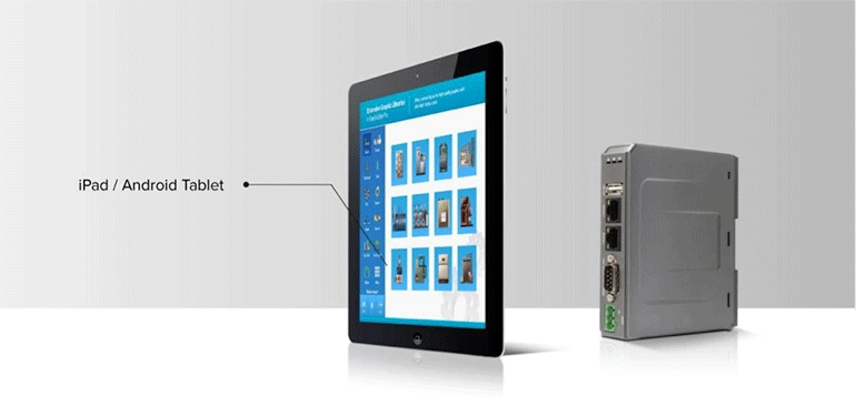


")