MAPware-7000 Programming Environment
MAPware-7000 is the configuration software used to program all our HMI+PLCs and PLCs. Use just one software application to program both the screens that appear in the display as well as the logic that controls your system. Create projects using the tools and graphic images included with the software to provide a functional user-interface for your control system. In addition, the built-in or expandable I/O can be used to control and monitor your system utilizing the logic instructions integrated in the software.

Tags
Tags are names assigned to internal memory registers of the unit, contacts of an expansion module, and any PLC data registers/coils of an external PLC.
Some system tags are predefined when you first begin a project. Other tags are created by the programmer. For example, you must create and assign a tag to every PLC memory address that you wish to read/write to. When using the optional I/O Expansion modules tags are created in order to use them.
- Tag databases can be moved from one project to another without copying the entire project.
- If you wish to modify many tags, this is quickly done by editing a CSV file.
- In some cases, you may be able to import the PLC addresses you use in your external PLC ladder logic program, thus saving time.
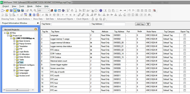
Tag Database
The Tag Database collects and stores all tags for review and editing. Once a tag is assigned, you can easily link any object (i.e. bit lamp, numeric register, etc.) to the tag. Tags have several advantages:
- Tags provide an organized method of tracking all memory addresses used in a project.
- Tags are much more descriptive of functionality than the name of the memory address.
- Tags are more easily edited, should a change be required.
- Tags can be exported and imported into other MAPware-7000 projects, regardless of which unit is selected.
Import/Export Tags
Tags can be exported from a project to the CSV file format and edited in Excel before importing them back into the project, or into another project. This saves time and allows for flexibility during project design.
Read more about Address Formatting and Ranges in the MAPware-7000 Programming Manual
Tag Usage
This feature allows you to select a tag in the tag database and view where it is used in your project:
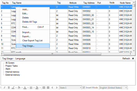
Read more about creating, adding, finding, editing, or deleting a tag in the MAPware-7000 Programming Manual. Or watch our video on Screens and Tags creation.
Controller Cable Wiring Diagrams
We offer hundreds of custom communication cable drawings for the industry’s most popular PLC manufacturers. Whether you want to build your own cable or have us build it for you, we can provide you with exactly what you need.
Refer to the Communication Cables in the Support Center.
Debug Mode
The Debug feature provides various functions that can be helpful when troubleshooting the ladder logic in your unit.
A debugger allows users to slow down the execution of a ladder logic sequence to a human time scale so that they can see what the unit is doing one ladder instruction at a time. This is the best way to understand what the unit is doing while it is occurring. The Debugger allows the user to set breakpoints to halt execution at a particular point in the logic and then step through, one instruction at a time, watching the data fields update at each and every step.
Tip: The Data Window provides an easy tool that can be used to debug your project. In addition, the Data Window can also be used to download preset values to the PLC for testing.
To use the Debug options, you must be online. Up to eight breakpoints can be set to pause logic operation at different points. The watch window can be used to monitor tags while debugging, and variable can be added or removed during runtime.
Supported debugging commands:
- Set Breakpoint ‐ set a breakpoint where you would like the logic to pause
- Go to Breakpoint ‐ execute logic up to the next set breakpoint
- Remove Breakpoint ‐ remove a breakpoint that is no longer needed
- Single Step ‐ execute ladder logic one instruction at a time
- Single Scan ‐ forces the ladder logic to perform a single scan, then stops at the current active step instruction
- Show/Hide Watch Window ‐ displays the watch window. Similar to the Data Monitor Window, the watch window is only available in Debug mode and is used to watch specified address tags
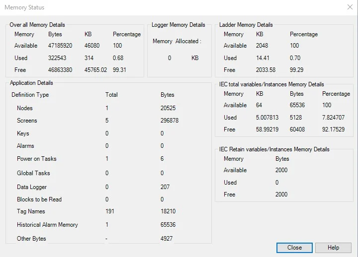
Memory Status Box
MAPware-7000 tracks the memory requirements of your project and displays the following information in the Memory Status box:
- Total memory available (varies by model)
- Memory used
- Memory free
- Logger memory allocated
- Ladder memory available, used, and free
- Application Details (bytes used)
- Nodes
- Screens
- Keys
- Alarms
- Power-on tasks
- Global tasks
- Data logging
- Blocks to be read
- Tag names
- Historical alarm memory
- Other bytes
For more information on the Memory Status box, see the MAPware-7000 Programming Manual.
Objects
Object Properties control an object’s appearance and function. The programmer can configure these properties using the Property Grid which displays the properties of the currently selected object. Most of the objects placed onto a screen share common properties such as color, border, label, line color, font, language, text, feedback, style, and overall properties.
Register Based Objects
There are many options for displaying and writing to 16/32-bit registers. Register-based objects display the value in an internal or PLC register and allow the operator to write new values. Register-based objects can also display predefined messages or images depending upon the ‘state’ or range of values in the register.
Tag Based Objects
Screens and tags are not useful in and of themselves. Tags contain data that represent machine operation, but without a means of interacting with this data there is no way for an operator to understand or control what the machine is doing. A programmer can place objects on the screen, exposing program data to the operator, and fulfilling the Human Machine Interface function of the unit.
Import/Export Text Objects
The Import Text Objects and Export Text Objects features allow you to export a listing of all objects that can display Multilingual (Windows fonts) text. This is particularly handy when using the Multiple Language feature. Instead of entering each language object-by-object in MAPware-7000, you can export to a CSV (comma-separated value) file, and then edit the file using another application such as Microsoft Excel.
For more information about this feature, refer to the MAPware-7000 Programming Manual.
Multi-Language Feature
The multi-Language feature enables the programmer to configure the project for use in many countries around the world that may use a different language. You can configure each object or text box with multiple labels, each designed for a unique language. During operation of the unit, display a screen that allows the operator to select which language he/she prefers to use. Once selected, all the objects and text boxes immediately depict the appropriate label.
- Configure projects in up to nine different languages
- Assign various languages to text using a Language Tag to display the correct language
- For international markets, create one project that can display text in different languages with the simple press of a button
The MAPware User Interface

Importing CSV or Excel Files
Tags can be exported from a project to the CSV file format and edited in Excel before importing them back into the project, or into another project. This saves time and allows for flexibility during project design.

Logic Editing Tools
Our HMI + PLCs support IEC 61131-3 programming language. Quickly find logical errors and complete your project in a timely manner.
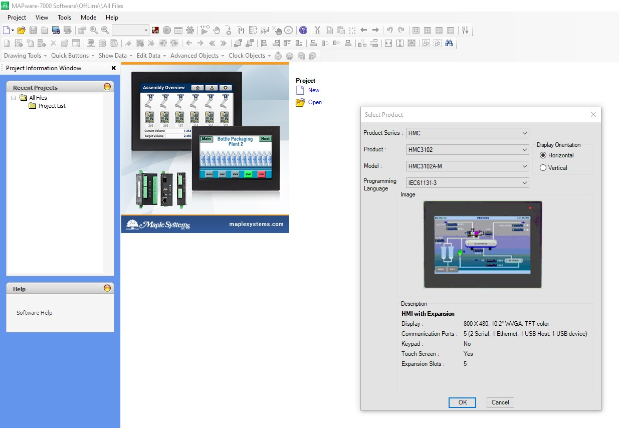
Easy To Understand Menus
MAPware-7000's user interface is divided into easy-to-understand categories and dropdowns, this makes finding objects and navigating the programming environment both user-friendly and efficient.
Off-line Simulation
Run your project in simulation mode, giving you the ability to test your project on the PC prior to downloading it to your unit. With the Offline Simulation option (Project > Run), the computer can display a copy of the HMI + PLC on-screen, simulating how your project will look and operate in the HMI + PLC. Logic simulation is also available with programming with IEC61131-3.
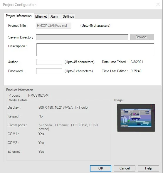
Project Configuration Tab
Conveniently located on the main navigation, the Project Configuration tab is the heart of the software. In addition to providing the programmer information like display resolution and the Comm port configuration for the selected unit, the programmer can name the project, add a password to project, add the ethernet settings, set-up alarms, and more as preferred.
Read more about the Project Configuration Tab in the MAPware-7000 Programming Manual.
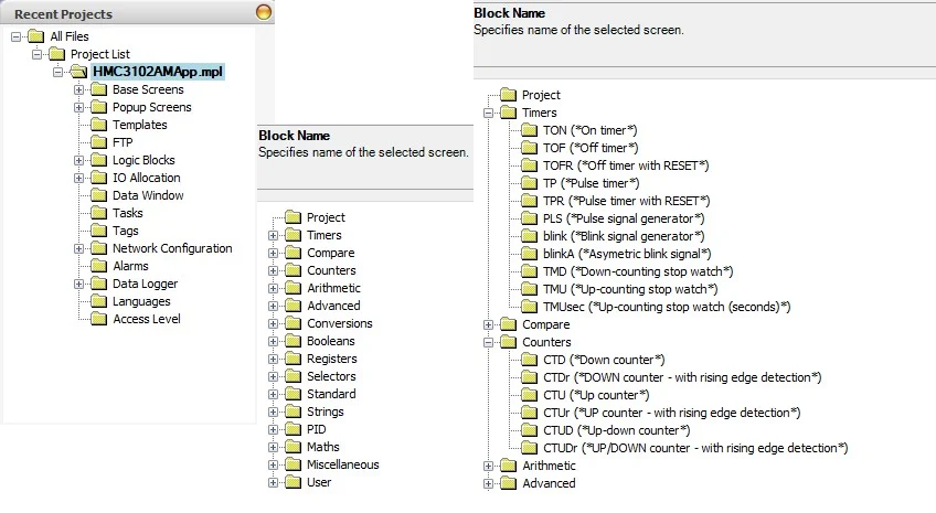
Window Tree Pane
View all of your project windows in a convenient tree-style list, with an expandable list of all elements and objects in each window.
Use the window tree pane for ease of navigation between project windows and quickly locate and select window objects and elements from a simple list.
Check the existing windows in the Windows Tree. The Windows Tree displays window numbers and window names. View the object ID, address and description of the objects used in this window.
Find and Replace
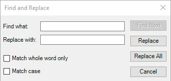
Using this window Find/Replace operation can be done for selected operand address or operand name for instructions within selected logic block. Click on one of the search instructions: Find in logic blocks, Find Operand, or Find Instruction.
Window Design Pane
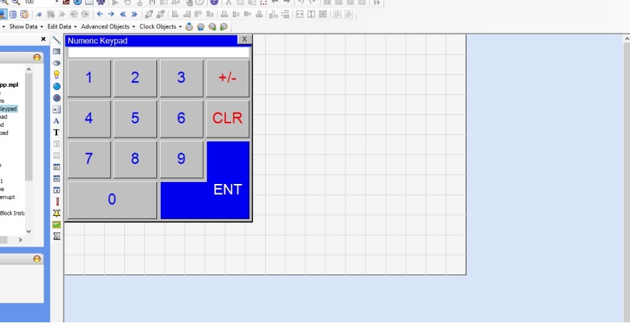
A graphical window design pane provides ease of design with window tabs, drag-and-drop and snap-to-grid functionality. Design your windows exactly as they will look on your project display.
Get started with MAPware-7000

Explore our MAPware Tutorials with easy to follow instructions, sample projects, and videos.