HMI+PLC Configuration Software Features
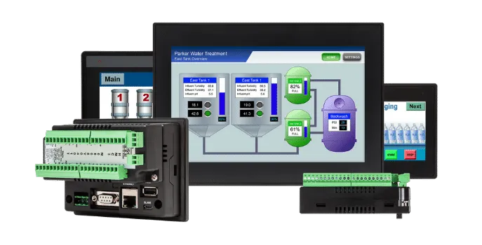
Our HMC series combines a touchscreen HMI and PLC all in one unit. Utilized worldwide to employ diverse applications, our HMI+PLCs lower costs, save space, and feature options including: Serial and Ethernet communication, support for Class I Division 2 installations, and numerous I/O configurations. What's more, they provide an affordable combination of display and control in a single package and programmed by using our Free MAPware7000 software with graphs, alarms, trending, data logging, web server functionality and more.
Advanced models unlock additional functionality such as MQTT, VNC Server, email, advanced graphics, recipe database, and much more.
| Software Features | |||||
|---|---|---|---|---|---|
|
Alarms
Display an alarm message on screen to notify the operator when a
parameter or process goes out of bounds.
Alarm Basics
Real-Time Alarms
Real-time alarms are programmed to trigger when certain events in
your process occur. Alarms display in real-time to show the current
status of a process. When real-time alarms are triggered, they
remain on the display window until they are acknowledged. The alarm
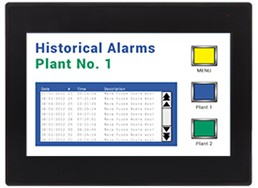
condition then returns to its normal state. Display real-time alarms with different text colors to delineate the state of the alarm (active unacknowledged, active acknowledged, or inactive unacknowledged), severity, date and time, etc. Historical Alarms
Historical alarms are a sequential history of your application's
alarm activity. Stored in non-volatile memory, they remain even when
the machine is turned off. Historical alarms can be displayed with
the severity level, date, and time the alarm occurred, when it was
acknowledged, and when it returned to normal. A historical alarm
list can also be uploaded to the PC and saved as a CSV file using
MAPware-7000. 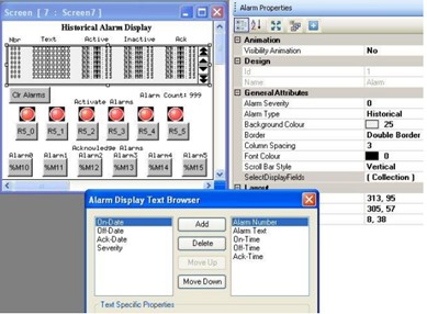
Alarm Configuration
Configure alarm Windows® with scroll bars
(left/right/up/down) to view long or wide alarm lists. Export the
alarm data in MAPware-7000 as a CSV file for editing, then import it
back into MAPware-7000.
Severity Categorization
Alarms can be categorized and filtered by severity by assigning one
of nine severity levels to each alarm. Then choose which alarm
numbers you wish to view. For example, easily view alarms with a
severity level of six or higher, etc.
Additional Useful Features
For more information on Alarms, refer to the MAPware-7000 Programming Manual or watch one
of our Training Videos:
Local Alarms in IEC Mode External Alarms in IEC Mode. How to Program Alarms See the Documentations and Resources tab for more information on our training videos, sample projects, manuals, and tech notes. |
|||||
|
Application Conversion and Import/Export
Options
MAPware-7000 provides a method for converting a project created for one
model into a project for a different model.
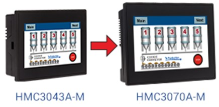
Application Conversion
Convert a project from one model and screen size to another
using the Convert Application tool. This allows you to take a
MAPware-7000 project developed for one model and use it on a
different model without having to recreate the project all over
again.
Import/Export Tags
Tags can be exported from a project to the CSV file format and
edited in Excel before importing them back into the project, or
into another project. This saves time and allows for flexibility
during project design.
Import Screens
Screens and their associated tags can be imported from another
project into your current project to speed the development
process. See our Support Center for our the MAPware-7000 Programming Manual, Getting Started Guides, Module Guides, Logic Guides, and training Videos all designed to help you get your project started. |
|||||
|
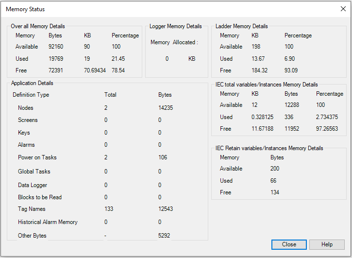
Application Memory Status
The Application Memory Status feature is a tool available in the
MAPware-7000 software that is used to display memory used by the current
project. This tool can be used to determine how much memory is still
available for new screens, ladder logic, etc.:
Memory Status Box
MAPware-7000 tracks the memory requirements of your project and
displays the following information in the Memory Status box:
Screens and their associated tags can be imported from another
project into your current project to speed the development
process.
Keep Memory Area and
Retentive Tags
See our Support Center for our the MAPware-7000 Programming Manual, Getting Started Guides, Module Guides, Logic Guides, and training Videos all designed to help you get your project started. |
|||||
|
Barcode Scanner
A Barcode Scanner display object can be placed on
screen that will display a string value sent to a register by a barcode
scanner connected to the HMC over USB.
|
|||||
| Custom Start Screen In MAPware V2.36 and newer, a custom boot up screen (HMC4000) or message (HMC2000, HMC3000) can be configured to display after the HMC has powered on and before the project has loaded. If no custom boot up screen is configured, the default "Maple Systems" boot up screen will display. | |||||
|
Data Entry
The Data Entry feature offers you a variety of methods to edit data in
the PLC.
Inputting Data
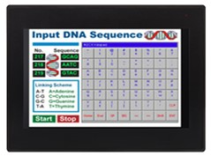
Alphanumeric ASCII Keypad
 Numeric Input Keypad
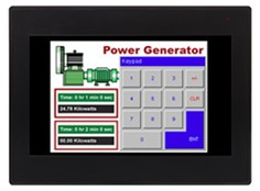
For more information on Keypads, refer to the MAPware-7000 Programming Manual.
|
|||||
|
Data Logging and Trend Graphs 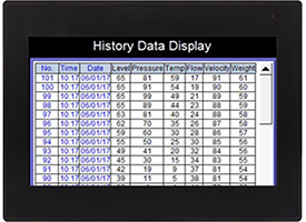
Data Logging
The Data Logger available in the HMC3000 series is used
to record values of tags over time. Data is collected and stored in
the
HMI + PLC's non-volatile memory or attached SD card and can be
displayed on the
HMI + PLC screen using the Historical Trend or Real Time Trend
objects. The
Data Logging feature is most often used for data acquisition where
the HMI + PLC
gathers and saves important process information for analysis.
Trend Graphs
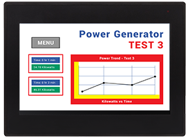 Use real-time trend and historical trend objects
to capture and graph data over a period of time:
Viewing Data
Collected data can be viewed several
ways:
Printing Data
Data Logger records can be sent to a serial
printer connected to the HMI + PLC.
|
|||||
|
The Data Monitor feature is a window available in the MAPware-7000
software that displays data values in unit's internal memory. The entire
internal memory of the unit is accessible using the Data Monitor but you
select what areas of memory you wish to monitor. In addition to reading
values, you can modify data online or create a table of preset values to
download to the registers. With this feature, you can quickly view data
in table format or to initialize areas of memory in the unit. In
addition to reading values, you can modify data online or create a table
of preset values to download to the registers. For more information on the Data Monitor feature, refer to the MAPware-7000 Programming Manual. |
|||||
|
Data Window
This handy feature is similar to a Watch window. It allows you to
construct a table of memory addresses that can be monitored from the
MAPware-7000 software while your PC is connected 'online' to a Maple
PLC.
Data Window
The Data Window provides an easy tool that can be used to debug
your project. In addition, the Data Window can also be used to
download preset values to the PLC for testing.
Additionally, the Data Window allows you to:
For more information on the Data Window feature, refer to the MAPware-7000 Programming Manual.
|
|||||
|
Debug Mode
The Debug feature provides various functions that can be helpful when
troubleshooting the ladder logic in your unit. A debugger allows users
to slow down the execution of a ladder logic sequence to a human time
scale so that they can see what the unit is doing one ladder instruction
at a time. This is the best way to understand what the unit is doing
while it is occurring. The Debugger allows the user to set breakpoints
to halt execution at a particular point in the logic and then step
through, one instruction at a time, watching the data fields update at
each and every step. To use the Debug options, you must be online. Up to eight breakpoints can be set to pause logic operation at different points. The watch window can be used to monitor tags while debugging, and variable can be added or removed during runtime.
Supported debugging commands:
For more information on the Debug feature, refer to the MAPware-7000 Programming Manual.
|
|||||
|
Email
The HMC4000 Series models can be configured to send an email when an
alarm triggers or at the press of a button.
Email Alarm Notifications
A critical process at a remote location requires attention. The HMC4000 can send an email to key personnel to let them know of the situation. A screenshot of an HMI window showing relevant data can be attached to the email or embedded if desired. Configure individual alarms to send an email to a specified group of recipients when the alarm is triggered. Create different groups (up to 16 groups) with various combinations of recipients for each group. Send Email with a Task
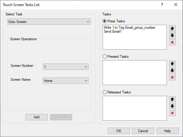
Use an Advanced Multitask Button to send an email. In the button properties, select Tasks and select "Send Email" from the dropdown menu. Specify the email screen numberm the screen name and the contact group to which the email will be sent.
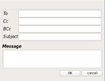
An email can be sent to a recipient specified at runtime using the Email on Fly task, which can be found in the task list for a Multitask Button. When this button is pressed on the HMI screen, a window will pop up that has entries for the recipient email(s), subject and message.
Configure Email
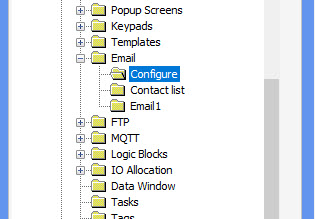
Configure the Email Settings by expanding the Email folder in the Project Information Window in MAPware-7000 (HMC4000 projects only).
|
|||||
|
Fonts and Languages True Type Fonts
Display text and labels with True Type fonts available on the
Windows® operating
system.
Multi-Language Feature
The multi-Language feature enables the programmer to configure the
project for use in many countries around the world that may use a
different language. You can configure each object or text box with
multiple labels, each designed for a unique language. During
operation of the unit, display a screen that allows the operator to
select which language he/she prefers to use. Once selected, all the
objects and text boxes immediately depict the appropriate label.
The Import Text Objects and Export
Text Objects
The Import Text Objects and Export Text Objects features allow you to
export a listing of all objects that can display Multilingual (Windows
fonts) text. This is particularly handy when using the Multiple Language
feature. Instead of entering each language object-by-object in
MAPware-7000, you can export to a CSV (comma-separated value) file, and
then edit the file using another application such as Microsoft Excel.
For more information on Fonts & Languages, refer to the MAPware-7000 Programming Manual or watch our video Multiple Languages. |
|||||
|
FTP Server
To use the FTP feature there must be an FTP server accessible at the
configured IP address. The FTP server must be configured with the user
and password specified and must permit write access for that user. The
SD card must be present and contain a log file to send.
Provided the above conditions are met, the unit will periodically upload a *.csv file to the FTP server. A new file is created each time the unit transmits data logger data to the FTP server. Each file will contain only the data recorded since the last file was sent. The name of each *.csv file consists of the file name specified for the group number, appended with the date and time information for when the file was sent. The period contained in each log file is determined by the Send File at Every field in the FTP Client Configuration window.
Logs are kept on the SD card that detail what data has been sent to
the FTP server. Data
transmission can be turned on or off with a button press. To use the
FTP feature, there must
be an FTP server accessible at the configured IP address. The FTP
server must be configured
with the user and password specified and must permit write access
for that user. The SD card
must be present in the HMC and contain a log file to send.
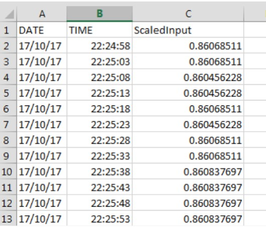 The MLC2 PLC model has an additional option when using the Data Logger feature described above. Data collected from the Data Logger can be transferred to a *.CSV file, then immediately sent to an FTP Server via the Ethernet port or one of the serial ports. For more information on the FTP Server, refer to the MAPware-7000 Programming Manual |
|||||
|
Functional Graphics
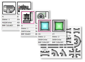
MAPware-7000 includes a large assortment
of functional graphic images to reflect the look and feel of
your operation. Use colored graphic images to indicate the
status of a process, the state of a device, or any action
you would like represented. Images are used to represent
objects including:
For the HMC4000 series, visible objects support color gradients. |
|||||
|
Importing and Exporting Tags
The tag database created in MAPware-7000 exports as a CSV
(comma-separated value) file. You can edit this file then import back
into MAPware-7000. This provides the following advantages:
Tag Usage
This feature allows you to select a tag in the tag database and
view where it is used in your project:
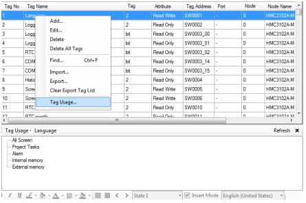
To read more about creating, adding, finding, editing, or
deleting a tag in the MAPware-7000 Programming Manual. Or
watch our video, Screens and Tags Creation.
|
|||||
|
Logic Blocks
Use ladder logic or IEC61131-3 programming to create the logic for
monitoring and controlling your system.
An important aspect of MAPware-7000 is
the ability to separate your PLC application into logic
blocks. Logic blocks help to keep your project organized and
easier to code. Up to 256 logic blocks can be created. In
MAPware-7000, there are five types of logic blocks:
|
|||||
|
Main Screen
The main screen in MAPware-7000 is divided into logical sections
providing access to many tools needed to create a unique graphic
display including: menus and toolbars, project information, screens
and logic block work area, and individual properties for selected
objects.
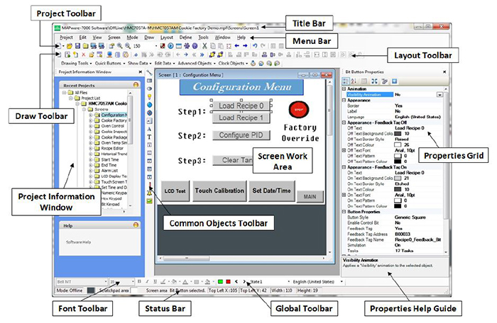 The MAPware-7000 configuration software provides access to many
basic tools
necessary to create a graphic representation of your control system.
Display
data in various formats, modify data, and create the underlying
logic to
monitor variables in the control system and respond accordingly. The
main
screen in MAPware-7000 is divided into logical sections providing
access to
many tools needed to create a unique graphic display including:
menus and
toolbars, project information, screens and logic block work area,
and
individual properties for selected objects.
The MAPware-7000 configuration software provides access to many
basic tools
necessary to create a graphic representation of your control system.
Display
data in various formats, modify data, and create the underlying
logic to
monitor variables in the control system and respond accordingly. The
main
screen in MAPware-7000 is divided into logical sections providing
access to
many tools needed to create a unique graphic display including:
menus and
toolbars, project information, screens and logic block work area,
and
individual properties for selected objects.The graphic shown displays main elements of the MAPware-7000 software screen: Menus and Toolbars
The upper section of the main screen contains the menus and
toolbars. The menus
and toolbars change depending on whether you are programming screens
or logic
blocks.
Project Information Window
The left section of the main screen displays the project in a
directory
structure with folders and subfolders for screens, logic blocks,
tags, alarms,
data logging, and I/O and network configuration.
Screens and Logic Block Work
Area
The middle section of the main screen is the work area for
developing your
screens and logic. Configuration Windows® also appear
here when
their corresponding folder is selected in the Project Information
Window.
Screen/Object/Instruction
Properties
The right section of the main screen displays the individual
properties for a
selected screen, object, or logic instruction and allows the
properties to be
edited.Useful Features
Additional Resources
Watch Video
Click the links below to watch videos: |
|||||
|
MAPware-7000 Introdution 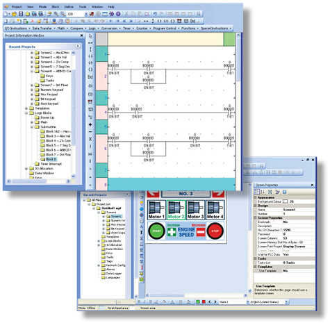 MAPware-7000 is the configuration software used to program all HMI +
PLCs. Use
just one software application to program both the screens that appear in
the
display as well as the logic that controls your system. Create projects
using
the tools and graphic images included with the software to provide a
functional user-interface for your control system. In addition, the
built-in
or expandable I/O can be used to control and monitor your system
utilizing the
logic instructions integrated in the software. The graphics program and
logic
program work together to provide complete control through the graphic
interface.
|
|||||
|
Meters and Bar Graphs
Display analog data such as temperature, voltage, current, and speed in
familiar easy-to-read
formats.
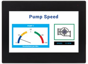
Meters
Analog meters display data on a circular scale. Use the meter's color
range to demonstrate safe to cautionary levels of operation. Display
data such as temperature, voltage, current, and speed in familiar
easy-to-read formats. Other features include:
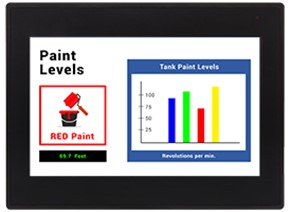
Bar Graphs
Bar graphs are used to display data on a vertical or horizontal scale,
with up to four bar graphs on a single scale. Other features include:
Multiple Bar Graphs
The Multiple Bar Graph object represents up to four consecutive
8/16/32-bit registers as a bar chart whose proportional lengths
correspond to the quantity in each register. A multiple bar graph can
move in any direction (i.e. left to right, bottom to top, etc.) and
monitor the target registers as signed/unsigned integer, BCD, or
floating point values. The Multiple Bar Graph object supports title
bars, selectable colors, and number designators along the
Y-axis For more information on Meters or Bar Graphs, refer to the MAPware-7000 Programming Manual |
|||||
|
MQTT
MQTT (Message Queuing Telemetry Transport)
is a lightweight, low bandwidth
protocol that works between clients and a broker (server) to publish and
subscribe data (topics) among
devices.
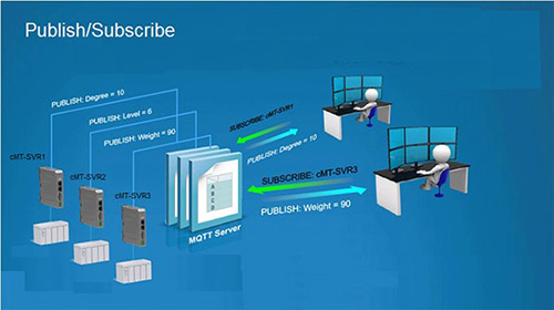
Maple Systems MQTT Integration
Maple Systems Advanced HMIs, Smart X Series HMIs and HMC4000
Series HMI PLCs all support the MQTT
standard version 3.1.1, while the HMC4000s will also support version
5. These products can function
both as MQTT Brokers (Servers) and MQTT Clients.
Typically, HMIs are used as MQTT Clients to publish process data to a central MQTT Server. Some examples of commonly used MQTT Brokers, which are supported by all Maple Systems MQTT-capable products, include Mosquitto, HiveMQ, RabbitMQ, and EMQX. The Smart cMT Series also supports Public Cloud Provider Integrations for MQTT, including those of Amazon AWS, Google Cloud, and Microsoft Azure. Additionally, the Smart cMT Series supports the Sparkplug B MQTT specification, which is designed to make it easier to track the state of sessions (connections) between the Client and Server. Various SCADA systems, such as Ignition by Inductive Automation, include built-in support for Sparkplug B, as does RabbitMQ via the MQTT plugin. Maple Systems Industrial PCs , Box PCs, and Panel PCs are the perfect host system for SCADA software and MQTT Server software. MQTT is supported in Web Studio SCADA software, the license for which can be bundled with your purchase of any Industrial PC by Maple Systems.
MQTT Topic Publisher
(Smart X Series only)
Data is organized into Topics in MQTT. Maple Systems HMIs can
publish data either periodically
(Time-based) or whenever a value changes (Trigger-based; a.k.a.
"Report by Exception").
Data are separated into individual Tags (values) and then published under a given Topic. MQTT Topic Subscriber
Any MQTT Client can subscribe to Topics via the MQTT Broker,
whether that Broker is running on
another HMI, or, as is more often the case, on another PC,
Cloud-based Server, or SCADA System.
Clients can subscribe to all topics, or just specific topics, from
the Broker.
Read more about MQTT, download supporting documentation, and find
out what Maple Systems hardware
supports MQTT, click here.
|
|||||
|
Objects – Bit/Coil Based
The MAPware-7000 software provides many options for displaying and
writing to bit/coil registers. Bit/coil registers are two state
registers that are used to represent an 'ON' and 'OFF' condition. Bit
registers often display lamps or buttons that control a target bit.
Bit Lamp
Bit lamps indicate the current state of a bit register using a
graphic image (i.e. lamp) or text (i.e. ON/OFF). When a bit lamp is
on a screen that is currently displayed on the unit, the unit
continuously polls the target bit register to determine which state
image to display.
Bit Display
Bit Display indicates the current state of a bit register using two
predefined messages (i.e. ON/OFF). The current value read in the
targeted bit/coil message determines what message displays. Messages
can be of varying length (maximum of 40 characters). When a bit data
display is on the screen, the unit continuously polls the target bit
register to determine which message to display.
Set-Bit
The Set Bit button sets a targeted bit/coil. The button displays
with either text labels or a graphic image to represent two states.
When a set bit button is on screen, the unit continuously polls the
target bit register to determine which state to display (feedback
tag must be enabled to display two states).
Reset Bit
The Reset Bit button resets (clears) a targeted bit/coil. The button
displays with either text labels or a graphic image to represent two
states. When a reset bit button is on screen, the unit continuously
polls the target bit register to determine which state to display
(feedback tag must be enabled to display two states).
Momentary Bit
When a momentary bit button is on screen, the unit continuously
polls the target bit register to determine which state to display
(feedback tag must be enabled to display two states).
Toggle Bit
The Toggle Bit button alternates setting and clearing a targeted
coil each time the button is pressed. When pressed by the operator,
the unit reads the current value of the coil, and then sends a
command to set or reset the coil depending upon the value read. The
button shows text labels or a graphic image that is used to
represent two states. When a toggle bit button is on screen, the
unit continuously polls the target bit register to determine which
state to display (feedback tag must be enabled to display two
states).
Bit Entry
Bit Entry is used to set/clear a targeted bit/coil. Two predefined
messages display according to the current value read in the targeted
bit/coil. Messages can be of varying length (maximum of 40
characters). When a bit entry is on a screen that is currently shown
on the display, the unit continuously polls the target bit register
to determine which message to display.
For more information on Bit/Coil based Objects, refer to the MAPware-7000 Programming Manual or watch one of
our videos:
Read and Write Objects Quick Buttons and Multi-Task Buttons Basic Objects and Animation Properties |
|||||
|
Objects – Register-based
There are many options for displaying and writing to 16/32-bit
registers. Register-based objects display the value in an internal or
PLC register and allow the operator to write new values. Register-based
objects can also display predefined messages or images depending upon
the 'state' or range of values in the register.
Word Lamp
Word lamps display predefined text labels or images shown according
to the 'state' of the target address. Each state represents a single
value or range of values tied to a particular text label or image.
The unit continuously polls the target register to determine which
state image to display. A maximum of 32 states are supported. Word
lamps are used where more than two choices are required. For
example, a tri-state condition with Run, Auto, and Manual modes may
be indicated using a word lamp.
Numeric Display
Numeric Display shows the current value of an 8/16/32-bit register.
The value can be displayed using a number of formats (i.e. signed,
unsigned, floating point), and special effects (ex. flash, color,
visibility). The numeric display object supports linear scaling
(engineering units) with the ability to scale the read value based
upon two mathematical operations. When a numeric display is on a
screen of the unit, the unit continuously polls the target register
to show the current value.
Message Display
Message Display shows a predefined set of messages depending upon
the value read in a targeted register. Messages can be of varying
length (max of 40 characters). Maximum number of messages is 255.
Note: if the value read from the targeted register is not within any of the predefined ranges, then the message displayed is blank. When a message data display is on a screen of the unit, the unit continuously polls the target register. Numeric Entry
The Numeric Entry shows the current value of an 8/16/32-bit register
and allows the operator the ability to write a new value. The value
displays using a number of formats (i.e. signed, unsigned, floating
point, and ASCII). The numeric entry object supports linear scaling
(engineering units) with the ability to scale the read value based
upon two mathematical operations. When a numeric entry is on a
screen of the unit, the unit continuously polls the target register
to show the current value.
Multi-Task Single-State Button
The Multi-Task Single-State button performs a set of predefined
tasks whenever the button is pressed. The button displays with text
labels or a graphic image that represents two states. When a
Multi-Task Single-State button is on screen, the unit continuously
polls the target bit register to determine which state to display
(feedback tag must be enabled to display two states).
Multi-Task Multi-State Button
The Multi-Task Multi-State button performs a set of predefined tasks
whenever the button is pressed. The tasks performed depend upon
which 'state' the button is in when pressed. The button displays
with text labels or a graphic image to represent the states.
Whenever the button is pressed, the object performs the programmed
tasks for that state. The unit continuously monitors a target tag
address to determine which state the button is in.
For more information on Register-based Objects, refer to the MAPware-7000 Programming Manual or watch one of
our videos:
Read and Write Objects Quick Buttons and Multi-Task Buttons Basic Objects and Animation Properties |
|||||
|
Objects – Tag Based
Screens and tags are not useful in and of themselves. Tags contain data
that represent machine operation, but without a means of interacting
with this data there is no way for an operator to understand or control
what the machine is doing. This section explores the various graphic
objects a programmer can place on the screen, exposing program data to
the operator, and fulfilling the Human Machine Interface function of the
unit.
General Object Properties
Object Properties control an object's appearance and function. The
programmer can configure these properties using the Property Grid
which displays the properties of the currently selected object. Most
of the objects placed onto a screen share common properties such as
color, border, label, line color, font, language, text, feedback,
style, and overall properties.
Flash Animation
Dynamically 'flash' selected object. 'Flash' means the object
displays on screen periodically depending upon the value in a tag
register. This can indicate an alarm condition or attract the
operator's attention.
Visibility Animation
Use this feature to make the object disappear. A tag address
monitored to determine when the object becomes invisible made
visible only when needed. This helps to reduce clutter on screen and
focus the operator's attention to the area of the screen that is
most important.
Flash
This is similar to the Flash Animation feature described above
except a tag register does not control this option. Therefore, if
enabled, the Flash feature continues as long as the object
displayed.
Simple Drawing Tools and Static
Objects
The MAPware-7000 software provides many drawing tools used to create
simple graphics on a screen. Sophisticated static objects are also
available to display graphics or text.
For more information on Tag-based Objects, refer to the MAPware-7000 Programming Manual or watch one of
our videos:
Read and Write Objects Quick Buttons and Multi-Task Buttons Basic Objects and Animation Properties |
|||||
|
Offline Simulation 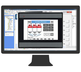
Run your project in simulation mode, giving you the ability to test your
project on the PC prior to downloading it to your unit. With the Offline
Simulation option (Project > Run), the computer can display a copy of
the HMI + PLC on-screen, simulating how your project will look and
operate in the HMI + PLC. Logic simulation is also available with
programming with IEC61131-3. (Note: Native Ladder Logic Blocks are not supported in Offline Simulation mode.)
For more information on Offline Simulation, refer to the MAPware-7000 Programming Manual.
|
|||||
|
Real-Time Clock
The internal battery powers the real-time clock (RTC) when the unit is
not powered by external 24VDC. Normally, the internal battery should be
able to provide power to the RTC for approximately 20 years (@25°C).
Reading the Date/Time
The Clock objects (Time and Date) are used to display the date and
time on an HMI + PLC screen. Each field of the RTC data can also be
read and individually displayed on screen by using the designated
system word registers (SW10 thru SW16) in the tag database.
For more information on the Real-Time Clock, refer to the MAPware-7000 Programming Manual.
|
|||||
|
Real-Time Monitoring
MAPware-7000 offers the ability to run your application on your unit
while going online with it and simultaneously monitoring the logic in
real-time from your PC. This important testing capability allows you to
monitor and analyze the functionality of your application as it actually
runs.
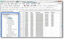
For more information on the Real-Time Monitoring, refer to the MAPware-7000 Programming Manual.
|
|||||
|
Real Time XY Plots 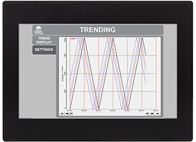
XY Plot (single point): Plot the value in one
register against the value in another register. A single point is
displayed on the plot, the position of the point changes as the
values in the registers change over time. Reference lines can be
added to the grid to help determine if the data points are within an
acceptable range. An error message will display along the bottom of
the plot when values are read that are outside the specified grid
range. XY Plot (multipoint IEC programming mode only): In this mode, data points (historic) previously recorded are not erased when new data points (current) are read. Up to 100 historic data points can be displayed. Data can be retentive so that it is maintained even if power is removed from the HMI + PLC. When the Data Point with Line and Line Only features are used, a line is drawn between each data point. Other features include:
For more information on the Real-Time XY Plots, refer to the MAPware-7000 Programming Manual.
|
|||||
|
Recipes
Easily manage batch processes by selecting different batch variables
used for a specific process with the simple push of a button.
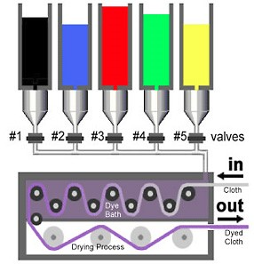
Using Recipes
A Recipe is an arrangement of internal registers in the unit's
non-volatile memory that are used for pre-defined process control.
The advantage of using recipes is in batch processing applications
in which a series of unique values or set points are required to
produce or perform an operation. If there are several different
batches or recipes, then the recipe features makes it easier for the
plant floor operator to select which recipe they need for the
current job, downloaded the preset values to the PLC from the HMI
with the press of a button, and start the job.
Transfer Recipe
The Transfer Recipe button is used to copy predefined constant
values from a consecutive set of internal HMI memory tag addresses
to a set of PLC memory tag addresses. Up to 100 values can be
transferred per button created.
Upload Recipe
The Upload Recipe button copies predefined constant values from a
consecutive set of PLC memory tag addresses to a set of internal HMI
memory tag addresses. Up to 100 values can transfer per button
created.
For more information on the Recipes, refer to the MAPware-7000 Programming Manual, or watch
our video,
HMC7000
Recipes
. Recipe Database
The Recipe Database is a feature in MAPware-7000 v2.36+ that when
enabled allows the user to create a local database of recipes,
organized into groups. Within MAPware-7000, recipes and groups can
be created, recipe data edited, and registers and bits can be
assigned to various functions so that recipes can be created,
edited, deleted, and searched for at runtime from the HMC screen.
Recipe data can be uploaded and downloaded to the HMC via USB drive
through the System Settings Menu or a task button placed on a
screen.
This feature is currently available for the HMC4000 series.
For more information on this feature, see our How to Program Recipes tutorial.
|
|||||
|
Remote Access
Select models have a built-in web server that allow the remote user to
both view and modify data in the unit. Screens are displayed in the web
browser as if it were a website. Only text-based objects and static
images are supported in this type of screen.
Web Screens
Select models have a built-in web server, accessible from any
Internet web browser, allowing remote access to HMI/PLC data from a
remote computer on the Ethernet network or, if exposed to the
Internet, from anywhere in the world. A username and password are
required, ensuring security. The screen is displayed in the web
browser as if it were a website. Web screens allow the remote user
to both view and modify data in the HMI + PLC. Up to 10 simultaneous connections are allowed. The objects used on web screens are restricted to text-based data display / input objects, static images and navigation buttons. Up to 100 screens can be created using MAPware-7000. Up to 100 objects (i.e. text, bitmaps, bit and register data values, and buttons) are available per screen. Ten users can be connected to the MLC3 PLC simultaneously. The following objects are available for use on web screens: 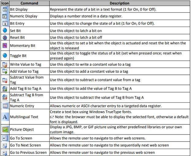
For more information on this feature, refer to the MAPware-7000 Programming Manual.
|
|||||
|
Screens
Create customized screens using graphic images included with the
software or personalize them with your own custom images.
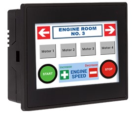
Screen Types
In MAPware-7000, you can configure or define a screen to be one
of the following:
Base Screen Create as many base screens as are required for your application. Use buttons or tasks to change from one screen to another. A base screen fills the entire area of the display.
Pop-up Screen A pop-up screen is displayed on top of a base screen and can be used to display additional information related to the base screen. A popup screen must be smaller than the underlying base screen.
Template Screen A template screen also fills the entire area of the display but is not called directly by a button or function key on the HMI + PLC. A template screen is displayed by attaching it to a base screen. When displayed, all objects on the template screen are underlayed on the base screen.
Keypad Screen A keypad screen is a specialized pop-up screen used to enter numbers or ASCII characters in a data entry display. There are four pre-defined popup keypad screens: numeric keypad, hex keypad, bit keypad, and ASCII keypad. These can be edited and custom keypads can be created.
Web Screen
Web screens are viewed by connecting to the HMI + PLC's built-in web server with an Internet browser. The HMI + PLC's web screens display in the browser as if it were a website, providing remote access to the unit for viewing system status information. See Remote Access feature for more information.
For more information on Screens, refer to the MAPware-7000 Programming Manual or check
out our Videos:
Getting Started with MAPware-7000 Part 5 and Part 6 Screen and Tag Creation |
|||||
|
Security and Passwords Access Levels
The Access Level feature available on select models allows you to
create users and passwords assigned to different access levels.
These levels can then be assigned to screens and used to restrict
access. When accessing a protected screen, a "Screen access denied"
error will show for users that have not logged in or do not have the
required level of access. Additional features:
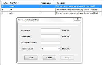
Protecting Project Screens
Screens can also be individually protected by creating a
password in the Screen Properties dialog box. Once entered, any
future operator must enter the correct screen password using an
on-screen numeric pop-up keypad in order to get to that
screen.
Intellectual Property ‐
Project Password
MAPware-7000 offers the ability to password-protect the entire
development project to protect your intellectual property.
Creating an optional project password is a way to protect your
project (and intellectual property) from unauthorized
modification. The password can be up to 8 alphanumeric
characters in length. If a password is created in the project
configuration window, the correct password must be entered to
open the project file for review or editing.
Note: A project password is not required. Care must be taken to remember the project password, as it is not recoverable if forgotten. It is not possible to recover a project if the password has been forgotten or lost. Remote Access
All remote access web screens are protected and require a
username and password.
Backlight/Screen Saver
Password Security
The HMI can be configured to go into a backlight/screen saver
mode after a predefined length of time, up to 90 minutes,
without any operator input. The operator reactivates the screen
by touching it, but a username and password can be configured
before normal operation is restored. This can be used as an
auto-logout type feature at the end of shifts, ensuring that
only authorized personnel can reactivate the HMI to begin the
next shift.
For more information on Security and Passwords, refer to the MAPware-7000 Programming Manual. |
|||||
|
Tag Database Tags are names assigned to internal memory registers of the unit, contacts of an expansion module, and any PLC data registers/coils of an external PLC. Some system tags are predefined when you first begin a project. Other tags are created by the programmer. For example, you must create and assign a tag to every PLC memory address that you wish to read/write to. When using the optional I/O Expansion modules tags are created in order to use them. The Tag Database collects and stores all tags for review and editing. Once a tag is assigned, you can easily link any object (i.e. bit lamp, numeric register, etc.) to the tag. Tags have several advantages:
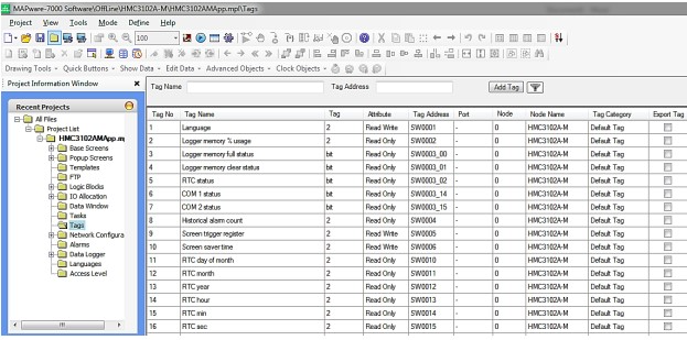
For more information on Tags, refer to the MAPware-7000 Programming Manual, or watch our video, Screen and Tag Creation, or Part 3 of our Getting Started with MAPware-7000, Adding and Initializing Tags. |
|||||
|
Tasks
tasks can be performed by pressing a button when a particular screen is
displayed or when the HMI +
PLC is powered on.
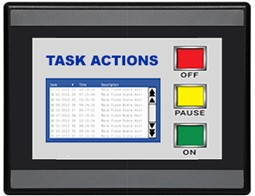
Task Actions
An integral part of the MAPware-7000 configuration software is the
ability to create tasks. Tasks are pre-defined actions executed by
the HMI + PLC program. More than 50 different actions can be
performed utilizing the Task feature. The number of tasks created is
limited only by the total amount of available memory in the HMI +
PLC. Actions include:
Task Triggers
Each task has two fundamental components: the action taken when the
task is activated and the triggering mechanism causing the action to
be performed. Tasks can be triggered when:
Assigning
Tasks
Tasks can be assigned to:
For more information on Tasks, refer to the MAPware-7000 Programming Manual, or watch
our video,
Tasks and Function Keys.
|
|||||
|
VNC Server
The HMC4000's built-in VNC server allows users to remotely monitor their process. For more information on this feature, see our How to Connect Remotely to an HMC4000 Series using the VNC Viewer Application tutorial.
Remote Monitoring and Control
All of Maple System’s HMC4000 Series HMCs possess a VNC server (included at no additional cost) which allows them to be remotely monitored from a number of devices (laptops, desktop PCs, tablets, and cell phones (iPhone, Droid, Blackberry, or any other smart device with VNC client capability).
VNC Server Benefits
In recent years, there has been a vast improvement in HMC remote monitoring abilities. Remote control of the HMC means remote control of the PLCs and controllers that command the automation process. This opens a new universe of logistical improvements in the control process. Monitoring your automation process from a remote location has never been easier and offers many process control benefits. What does that mean for the everyday operation of your plant?
Real-Life Applications
|
