What is a Programmable Logic Controller (PLC)?
Working behind the scenes in countless systems, Programmable Logic Controllers (PLCs) are responsible for controlling many processes that have become essential to modern life. This article will cover what PLCs are, how to use them, and some tips on how to choose a PLC that will work for you.
What is a PLC?
PLCs are rugged, compact computing devices that are purpose-built for use in control systems. Developed as a replacement for traditional electromechanical components, PLCs are extremely versatile devices that can collect data, execute complex control logic, and send commands to many types of machines such as conveyors, actuators, drives, and more.
At a minimum, a PLC will consist of a CPU used for processing, and an I/O terminal that enables communication with machinery.
How Does a PLC Operate?
PLCs operate by repeating a programmed loop known as a scan that will perform three fundamental tasks: reading input, executing program logic, and sending output to connected devices.

Input
In the first stage of a scan, the PLC will detect the state of connected devices to be read as input. This input may be in the form of a digital signal coming from a simple switch or push-button, or as an analog signal for more complex measurements such as those coming from thermocouples or pressure sensors.

Program Logic
The next phase of the scan will run the input values through the PLC’s program logic. The actual logic will vary depending on the processes, but will generally consist of a series of arithmetic operations that will transform input values into a desired output.
Program logic is created using the PLC’s programming software and may be written using one of several languages. Most commonly-used languages are capable of performing similar operations, so the language used will largely depend upon what the PLC software supports and the preference of the person responsible for programming.

Output
Running the input through the PLC’s program logic will result in output values that it can pass to other devices. Output signals transfer through the I/O terminal to external devices such as conveyors, valves or actuators.
Once the output stage is complete, the PLC will repeat the entire scan process again, starting with input collection. Repeating this loop allows the PLC to collect feedback, process it, and then adjust the behavior of devices accordingly to ensure reliable and efficient operations.
Advantages of Using a PLC
Why use a PLC instead of other solutions such as electromechanical controls? Compared to the alternatives, PLCs provide several advantages that have contributed to their widespread adoption across multiple industries.

Compact Design
Compared to traditional control systems, PLCs are far more compact and portable, capable of managing hundreds of feedback and control functions that used to require an entire room full of instruments.
Energy Efficiency
PLCs can operate very efficiently, consuming minimal electrical power compared to alternative control solutions. This helps conserve energy, and contributes to overall cost savings and sustainability efforts.
Reliability
With decades of refinement and testing, PLCs are a mature technology supported by extensive research and documentation. This wealth of knowledge facilitates seamless integration and ensures dependable performance in diverse industrial environments.
Cost-Effectiveness
PLCs are available across a broad price spectrum, including budget-friendly models suitable for small businesses and startups. This affordability enables organizations to leverage advanced control capabilities without breaking the bank.
Versatility
PLCs offer unparalleled flexibility, capable of controlling a wide array of processes and systems. Whether managing manufacturing operations, regulating environmental conditions, or overseeing machinery, PLCs provide adaptable solutions for various industrial applications.
Durability
As solid-state devices, PLCs boast robust construction devoid of moving parts. This inherent resilience makes them highly reliable, capable of withstanding harsh conditions commonly found in industrial settings without compromising performance.
That said, there are rare cases in which a PLC may not be the best choice for a control system. For example, extreme environments or local regulations may prohibit the use of electronic components in certain situations. In cases like these, an electromechanical control panel may be a better fit.
Choosing a PLC
Selecting the right Programmable Logic Controller (PLC) is critical for ensuring the effectiveness and efficiency of your industrial automation system. Consider the following key factors when evaluating PLC models for your application:

Power
There are two distinct categories to consider regarding a PLC’s power requirements: the power supplied to the entire unit, and the voltage levels assigned to the I/O terminal. Make sure that the PLC’s voltage requirements align with the facility’s electrical system and the devices it will be connected to.

Processing Speed
Assess the CPU speed of the PLC to ensure it can handle the processing demands of your application. It may be best to choose a model with sufficient processing power to meet your current requirements as well as some additional overhead for future expansion.

Compatibility
Check the PLC’s compatibility with your existing system hardware, including power supplies, I/O modules, enclosures, and mounting solutions. Researching compatibility before buying can ensure seamless integration and reduces the risk of delays during installation.

Environment
Evaluate the PLC’s tolerance to hostile environmental conditions to ensure safe and reliable operation in your facility. Consider factors like ambient temperature, explosive atmospheres, moisture, dust, or any other challenges specific to the location.

Connectivity
Assess the PLC’s connectivity options, including I/O ports and communication interfaces. Ensure it can connect seamlessly with the peripherals and devices required for your automation system, such as sensors, actuators, and communication networks.

Memory
Adequate storage memory and RAM (Random-Access Memory) are essential for efficient PLC operation. Ensure the PLC has sufficient memory capacity to store input and program instructions while executing functions smoothly.

I/O
PLCs may come equipped with digital or analog I/O support, but this will vary between models. Digital I/O is great for handling simple push button controls, but applications that require precise measurement instruments such as thermocouples and pressure sensors will require analog I/O in many cases. Consult the device’s datasheet to make sure that the PLC has enough I/O points to handle all required connections.
By carefully evaluating these considerations, you can select a PLC model that meets your specific application requirements, ensuring optimal performance, reliability, and compatibility with your industrial automation system. For tips on choosing the right PLC, check out our “10 Things to Consider When Choosing a New PLC” buyer’s guide.
Setting Up a PLC
Installing a PLC involves several steps, some of which will depend on the specific brand and model of the PLC. The following guide provides a general outline of the steps that are typically required to get a PLC up and running, but consulting the manufacturer’s documentation for specific instructions is recommended to ensure that nothing is missed during this process.

Install Programming Software
First off, you will need to download and install the programming software for your PLC. This is usually a proprietary application that the PLC manufacturer will allow customers to download from their website.

Create a New Project
Open the programming software and create a new project. You’ll need to specify details such as the PLC model you’re using and the communication interface (e.g., Ethernet, USB) to connect to the PLC.

Configure Hardware
Define the hardware configuration of the PLC within the software. This involves specifying the types and locations of I/O modules, as well as any additional hardware connected to the PLC, such as communication modules or special function cards. This process may also involve mapping physical inputs (e.g., sensors, switches) and outputs (e.g., actuators, valves) to memory locations within the PLC.

Write Program Logic
The next step is to develop the program logic using the programming software provided by the manufacturer. This is the core of what makes a PLC function, defining how it will process input data during operations. Once the logic is complete, the program will need to be compiled so that it can be installed and executed on the PLC.
Your PLC software may support multiple programming languages, allowing you to choose the language that works best for you. For more information about PLC Programming Languages, refer to the section below.

Download Program
Once you’ve written and compiled your program logic, it will need to be downloaded to the PLC. This process transfers the program from the development PC to the PLC memory. The program may be transferred through a network or USB port, depending on device support.

Test and Debug
Test the PLC program in a simulated or offline mode to verify its functionality. Check for any logical errors or unexpected behavior and debug as necessary. Once you have thoroughly assessed the program’s operation, you can confidently implement it into real-world applications knowing that your program logic is sound.

Online Monitoring and Maintenance
After deploying the program to the PLC, online monitoring tools provided by some manufacturers will allow you to monitor the PLC’s operation in real-time. This allows you to diagnose issues, make adjustments, and perform maintenance tasks as needed while the PLC is running, enabling you to optimize your processes over time.
Throughout the programming process, it’s important to follow best practices for PLC programming, such as organizing your code effectively, documenting your logic, and implementing safety measures to ensure reliable and safe operation of the industrial automation system.
PLC Programming Languages
Programmable Logic Controllers (PLCs) can be programmed using several different programming languages, depending on the manufacturer and model of the PLC. Below are some of the most commonly used PLC programming languages, with examples of a single function written in each language for reference.

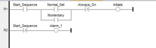
Ladder Logic (LAD)
Ladder Logic Diagram is the most traditional and widely used PLC programming language. It mimics electrical relay logic (on/off states) and is visually represented in a format resembling a ladder, with rungs representing control logic. Ladder Logic is particularly user-friendly for those with a background in electrical engineering or relay control systems. It is best suited for simple control systems and applications where binary decisions are predominant.
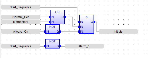
Function Block Diagram (FBD)
Function Block Diagram is a graphical language that uses blocks to represent functions, with lines connecting them to define relationships. Each block can represent a simple function like a timer or a more complex operation like a mathematical function. FBD is particularly effective for process control and applications involving complex mathematical operations. It is user-friendly for those with a background in control systems and process engineering.
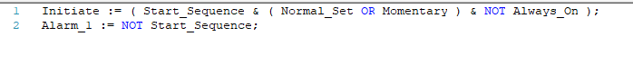
Structured Text (ST)
Structured Text is a high-level textual programming language that uses statements like languages like Pascal or C. It is suitable for complex applications that require algorithms, data processing, or tasks that are difficult to represent graphically. ST is best used in applications requiring complex control processes, calculations, and data manipulation.
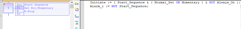
Sequential Function Chart (SFC)
Sequential Function Charts are used to describe the sequence of control operations in a system. SFCs are graphical and represent a process flow, making them ideal for sequential control processes and tasks that require coordination of multiple operations or stages. They are especially useful in batch processing and applications where the sequence of operations is a critical aspect.
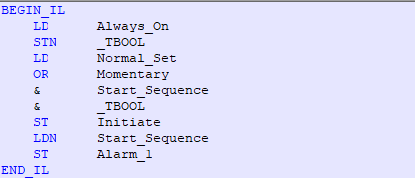
Instruction List (IL)
Instruction List is a low-level programming language like assembly language. This text-based language consists of a series of instructions, with each representing a different operation. Its compact and efficient nature makes it suitable for applications with limited memory and processing power. However, it requires a good understanding of programming concepts and is less intuitive than graphical languages like Ladder Logic.
While these programming languages offer the same functionality in most cases, your choice can significantly impact the development time, ease of maintenance, and scalability of your control systems. Selecting the right programming language depends on the specific requirements of your application, the complexity of the tasks, and the background of the personnel involved in programming and maintenance.
PLCs in SCADA Systems
PLCs play a crucial role in Supervisory Control and Data Acquisition (SCADA) systems. Coupled with the right HMI or Industrial PC, PLCs are used as the backbone of SCADA systems that enable precise measurement and control. Below are some of the essential functions a PLC may be responsible for within a SCADA system:
Data Acquisition
PLCs can interface with various field devices and sensors within an industrial process, collecting data on parameters such as temperature, pressure, flow rate, and levels throughout a facility. This data can then be transmitted to the SCADA system for monitoring and control.
Control and Automation
PLCs execute control logic based on the data received from sensors and programmed instructions. They regulate actuators, motors, valves, and other devices to maintain desired process parameters or perform specific tasks. PLCs ensure precise control and automation of industrial processes according to predefined algorithms and operational requirements.
Communication
PLCs serve as communication gateways between field devices and the rest of the SCADA system. PLCs may use common communication protocols such as Modbus, Profibus, Ethernet/IP, MQTT, or OPC to exchange data with other devices on the network.
Data Processing and Analysis
PLCs may perform basic data processing and analysis tasks, such as filtering, scaling, or averaging sensor readings before transmitting them to the SCADA system. This helps improve data quality and reduces the amount of unnecessary data transmitted over the network. Some PLCs also support advanced data analysis capabilities, enabling predictive maintenance, fault detection, and optimization of industrial processes.
Fault Detection and Alarm Handling
PLCs can detect abnormal conditions, equipment failures, or process deviations in real-time, and trigger alarms or notifications accordingly. PLCs play a vital role in ensuring operational safety and minimizing downtime by promptly identifying and responding to critical events.
Integration with HMI
PLCs interface with Human-Machine Interface (HMI) devices, allowing operators and engineers to visualize process data, monitor equipment status, and interact with the control system. HMIs provide graphical representations of the industrial process, real-time data visualization, trend analysis, and control capabilities. PLCs transmit data to HMIs for display and receive operator commands for manual control or adjustment of process parameters.
In summary, PLCs can manage the sensors, controls, processing, and fault detection processes that are at the heart of most SCADA systems. Integrating the right PLC into a SCADA system enables efficient monitoring, control, and optimization of countless industrial processes.
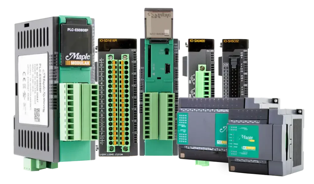
PLCs by Maple Systems
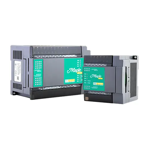
Micro PLC
These compact PLCs are designed for small scale use when simplicity and affordability merge. Ideal for specialized processes or incorporated into a larger system.
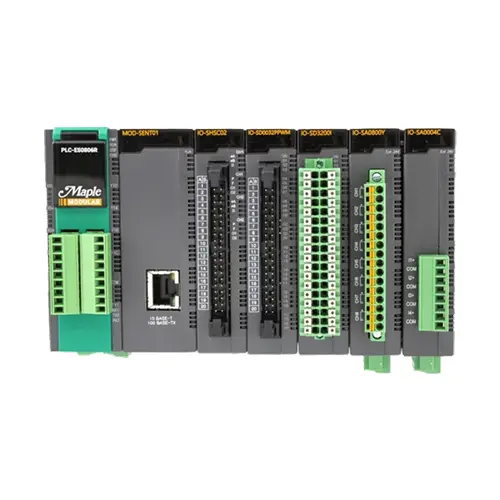
Modular PLC
Maple Systems scalable PLC line was created for a wide range of applications capable of adapting to your specific needs. With 15 I/O modules to choose from – this PLC is perfect for your complex solutions.
Advanced PLC Features
Whether you have an all-in-one Micro PLC or the expandable Modular PLC with up to 11 I/O modules, we can add functionality to your project with our advanced features.
PID Auto-Tuning
Quickly tune parameters for your PID loop using the automatic PID tuning function. Check out our “What is a PID Controller?” tutorial.
Online Editing
Make live changes to your program logic without stopping operations. Watch our tutorial “How to Use the PLC Simulator and Online Editor” to learn more.
Input Filtering
Eliminate noise from input signals with the Digital Input Filter, IO Input Filtering, and Standard Input Filtering features in MapleLogic.
Security
Safeguard your project. Maple Systems’ PLCs and software allow you to set passwords for your entire project, program, or individual function blocks.
Pulse Width Modulation (PWM)
Control variable load devices such as DC motors and VFDs with precision. See the “What is Pulse Width Modulation?” video tutorial for information on how to use PWM in your project.
Simulation
Run your project in simulator mode, giving you the ability to test your project and verify your changes on your PC before you download to your unit. For more information, see our “How to Use the PLC Simulator and Online Editor” video tutorial.
Interrupt Routines
Interrupt routines will pause the PLCs main program logic when a specified event occurs, allowing the system to safely manage the event before resuming the normal program scan.
High Speed Counter (HSC)
A high speed counter is used for counting the number of pulses received in an assigned high-speed digital input. It can provide high-speed output signals for stepper motor control, alarms, or other discrete control functions. Check out “How to Program a High-Speed Counter” in our tutorial series for more information.