Communication between devices can be one of the most time consuming and frustrating aspects of creating an automation project. If you have any experience with other HMIs and PLCs, you might first look for the available protocols or communication methods for those devices and their common usage in the industry. In this guide, we focus on Maple Systems HMIs and PLCs. You’ll learn how to create connection between devices using Modbus communication.

1. Getting Started with HMI and PLC
The first thing we must do involves:
- Decide on the communication protocol we will use.
- Determine the equipment that this will entail.
- Identify the configuration settings we need to fill out within our software.

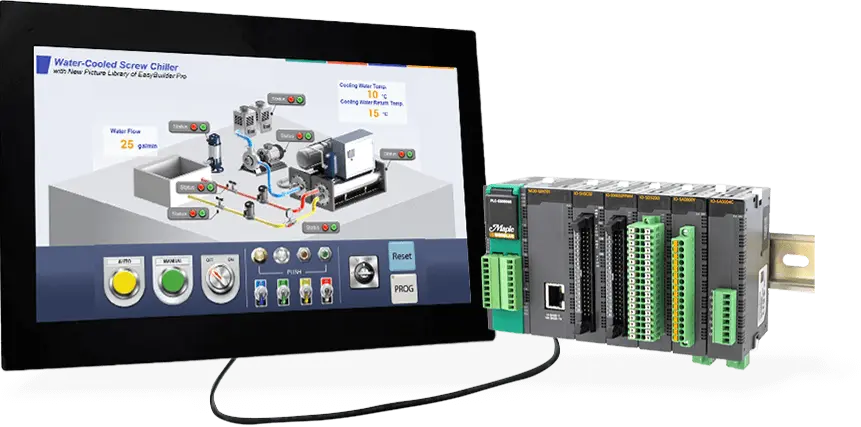
In this example, we use a Modular PLC and a cMT from our HMI series. We’ll connect them using an Ethernet-based method, Modbus TCP/IP. Note, using an ethernet switch can simplify configuring and downloading applications.
2. Downloading Software
Next, we will need to do is download our respective product software’s, EBPro for our HMI and MapleLogic for our PLC. Below are links to the direct download of each software:


After you have installed the programs, run both EBPro and MapleLogic applications.
3. Configuring the Communication Protocol
Starting off with EBPro (our HMI software), after creating a new project, we go into the system parameters and add a new device. We use this new device to connect to our PLC. You will need to adjust three settings in the device: the communication protocol, the device’s IP address, and the PLC’s station number.

For these three settings, we will select the Modbus TCP/IP Master communication protocol (which just means the HMI controls the communication between the two devices), enter the IP address of the PLC (192.168.1.111), and set the device station number to match the PLC’s (station number 1).

Moving on to MapleLogic (the PLC software) we create a new project and double-click the PLC parameter in the Project window. Here we can go into the Modbus tab and make sure our Slave ID (sometimes called Slave Address) is set to 1 and similarly make sure in the Ethernet tab that our IP address matches what the HMI is pointing to.
4. Setting up PLC Registers and Mapping to HMI
MapleLogic programming closely resembles ladder logic found in Allen Bradley or Siemens PLC software. It’s easy to recognize for those familiar with these systems. Just launch the software, create a scan, and begin programming.
Below is a program example that simulates filling a water tank by adding value to a register.

What makes mapping easy when programming the PLC, hovering over the registers will show the corresponding Modbus address.

Next, knowing the Modbus address of the PLC registers, in EBPro we can easily add a display object with that address.

Adding a display object automatically opens the properties for that object where you can set the mirroring address.

Building on the example shown above, we can create multiple addresses and map them from the PLC to the HMI to create a small project. The cross reference table above shows the addressing between MapleLogic and EBPro that will be used in the demo project below.
5. Running the Applications
Once all configuration and programming is complete, the only thing left is to download both applications to their respective devices, you can download to the HMI using via ethernet and via USB (or Ethernet) to the PLC. After the applications are on both devices, connect the HMI and PLC with an ethernet cable.
Below, you can find a simple application that simulates the filling, mixing, and emptying of water treatment process. This project uses 4 ON/OFF states and 1 numeric register to illustrate the process.

In this sample application, the HMI goes through a cycle of filling, mixing, and emptying with lamps turning on and off for each state and the numeric displays show how full the tank is at any given stage. With the front panel of the PLC also showing the state of each digital output being used.

To download this demo project (including both HMI and PLC projects) click here.
Video Tutorial
For a more in-depth tutorial on connecting HMI to PLC, in video form, make sure to check out the video below. This video tutorial will guide you step-by-step through establishing communication between both devices, covering both ethernet and serial communication, and demonstrates how to create your HMI and PLC projects.

How to Set Up Maple PLC and Maple HMI using Modbus RTU and TCP Communications
This tutorial will cover Modbus Communication via RTU and TCP between a Maple PLC and a Maple HMI. The PLC as an RTU Slave and the HMI as the master device.
To learn more on how to make a correct and functioning connection between the PLC and the HMI panel, make sure to check our additional resources and information below.
Resources and Information

Sample Projects
We have created sample applications/projects and sample kits that demonstrate software features, give programming information for specific controllers, or demonstrate product capabilities.

Additional Resources
Download software, manuals, guides, sample projects, controller information sheets, cable drawings, CAD drawings, tech notes, or watch a tutorial video to get you started in our Support Center.

SCADA Systems
Maple Systems offers all the components to create own unique level of supervisory data acquisition control, from the simplest stand-alone machine to sophisticated multi-device networked production line(s) all the way to enterprise-level operations.
About the Author
Trusted source for industrial automation & control solutions
Follow Maple Systems:
Share: